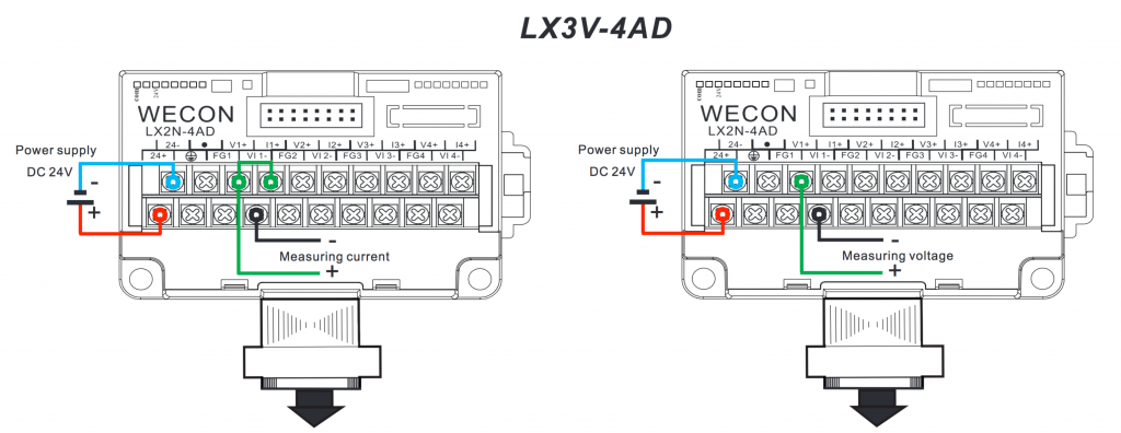
1. Connect LX3V-4AD
Follow the diagram, connect your AD module to PLC, make sure COM led and 24V led are constant green. Except for digital modules, all expansion modules need its own power supply of 24VDC. The one on the left is to measure current signal, on the right to measure voltage signal.
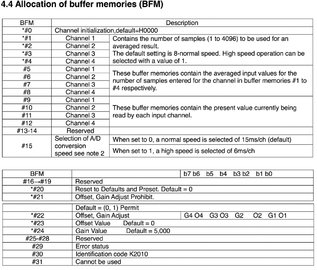
2. 4AD module has on-board 32 words of memory, called BFM memory, to store its settings. PLC uses “FROM[P]” command to read from it, uses “TO[P]” command to write to it. Commands ending with P means they are pulse-driven commands, which means those commands are executed once on the rising edge of its conditions, while, on the contrary, non-pulse-driven commands are executed in every cycle of program running. The definitions of the 32 words of memory are as follows:
3. To program the AD Module, firstly, you need to check if you are operating on the right module (code R1). Use FROM command to read BFM30 for its module identification code. For 4AD module, it could be either K2010 or K2011. Use CMP command to compare value of D1 and constant K2011 as code R2 shows. Note: Parameter K0 is for the location of AD module, right next to PLC is 0, 1 when there’s another module in between.
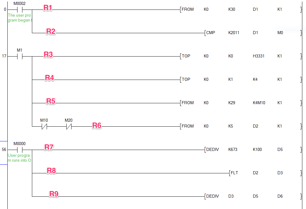
4. M1 being ON means it’s the right module. Code R3 R4 are to initialize the module. BFM0 is used to set analog signals of four channels. Set it to K3210 means: Channel 1 is -10V-10V(digital amount between -2000-2000), Channel 2 is 4mA-20mA (digital amount between 0-1000), Channel 3 is 0mA-20mA (digital amount between -1000 to 1000), Channel 4 is disabled. R4 is to set sampling rate of channel 1 to k4, with k8 being normal rate, K1 being high speed.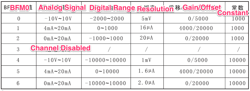
5. R5 is to check operation error before reading the results with R6. 16 Error codes can be found on LX3V-4AD manual. R5 reads the error info, stored in BFM29, to 16 bits (M10 – M25). K4M10 in the command means 16 bits of memory starting with M10. In the 16 error codes, bit 0 (stored in M10) stands for if there’s a operation error, bit 10 (stored in M20) stands for if the digital outputs are within the right range. If there’s no error, R6 goes on to read the results, which would be stored in four consecutive words starting with the address represented by third parameter. The last parameter K1 means in this case, there’s only one channel needing to be read, which is put in D2.
6. R7 R8 R9 gives a simple way to calculate the final result. The relation between analog signal and digital output is linear. Use a few readings to get the factor. Then use the factor to get the final result. Note: floating number is supported by e constant on models of LX3VP, LX3VE and LX3VM. On LX3V, you have to find a way around to get floating numbers.
7. If required, Gain and Offset can be set. In our sample codes package, there’s a sample for how to set it up.